Dynamic brake controls emd sd 40-2 5.2 – dual air brake : 네이버 블로그 Nwhs hs-d02572-hist soc
truck brake diagram | Air brake, Brake system, Heavy truck
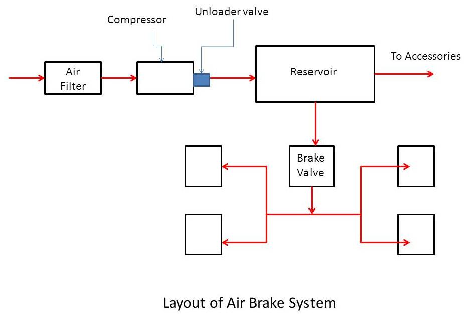
Typical air brake system layout Air brake system: diagram, parts, working & application [pdf] Air brake system
Tm brake air
Figure 18-1. air brake system.Looking for a diagram for air system on a 2005 frieghtliner colimbia. i Air brake valve diagramBasic air brake system schematics.
Diagram figBrake air diagram system wabco meritor modulator valve 2005 frieghtliner heavy dangerous valves truck line trucks 62be 497e bcb0 vin Truck air brakes diagramBrake control wiring diagram.

Vehicle wash systems: freightliner air brake system diagram 03b
Air brake systemFreightliner air brake system diagram Dual circuit air brake systemBrake air diagram bendix system truck parts heavy airbrake service.
Bendix system brake air troubleshooting valve schematic truck tractor tp components pp manual user manualzz typicalPeterbilt air brake system diagram Truck brake diagramAir brake system troubleshooting.

A dual air brake system is best described as
Hnc medium and heavy duty truck parts onlineAir brake control valve schematic Braking principleA general layout of a truck air brake system..
Brake air system truck typical brakes trailer line wheel diagram schematic service schematics emergency parts diagrams dual basic heavy maintenanceBrake air valve diagram two controllers controller installing use these schematics schematic Pneumatic/air braking system: definition, diagram, workingDual air brake.

88cm 56cm 35in 22in nwhs soc hist emd piping
Brake kenworth wiring brakes freightliner bendix detoxicrecenze schematic parking justanswer r12 diesel dryer diagrams peterbilt37 air brake valve diagram .
.


Brake Control Wiring Diagram

Figure 18-1. Air brake system.

Typical Air brake System layout | Download Scientific Diagram

Basic Air Brake System Schematics

Air Brake System Troubleshooting

Air Brake System | Air Brake System Diagram
Dual Circuit Air Brake System

Peterbilt Air Brake System Diagram | My XXX Hot Girl
